

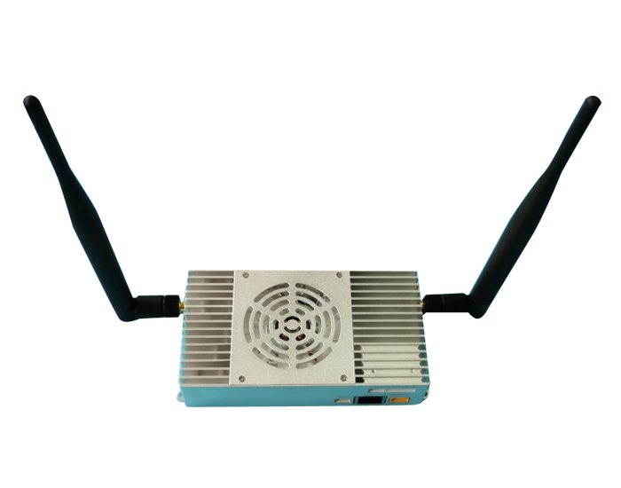
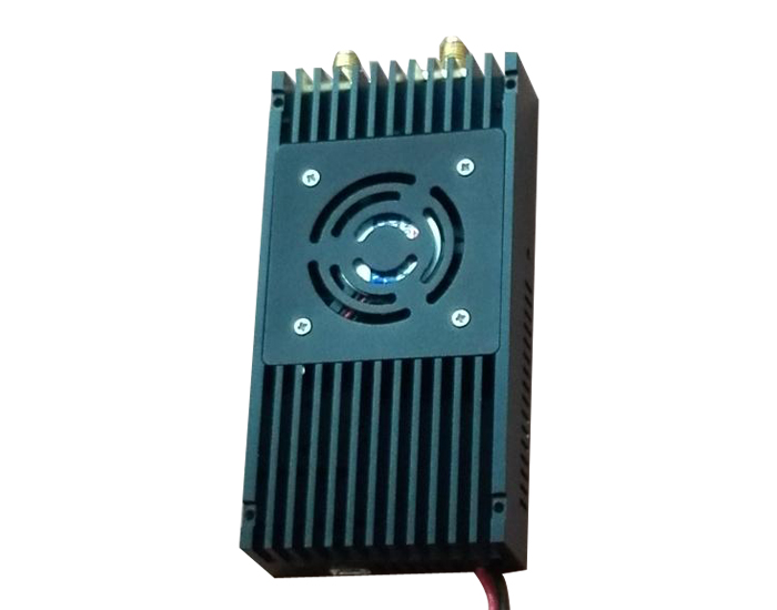
AJ-DLS150K-10 wireless link equipment to achieve long-distance two-way wireless video, audio, data transmission, air-to-ground transmission distance up to 150km or so.
AJ-DLS150K-10 wireless link equipment to achieve long-distance two-way wireless video, audio, data transmission, air-to-ground transmission distance up to 150km or so. The AJ-DLS150K-10 device provides multiple service ports, including two Ethernet ports, three serial ports, and audio input and output ports.

AJ-DLS150K-10 Bi-directional broadband wireless link equipment Technical specifications
> Bidirectional broadband wireless link equipment based on OFDM technology.
> Service ports: 2 Ethernet ports, 3 RS232 serial ports, audio input and output ports
> Dual antenna: SMA connector, ANT1 main antenna works in send and receive mode, ANT2 auxiliary antenna works in receive mode.
> Wireless operating band: 1428~1448MHz or 806~826MHz, support automatic frequency hopping within the frequency band
> Wireless bandwidth: 3MHz, 5MHz, 10MHz, 20MHz, all nodes share the working bandwidth, the maximum sharing rate of the system 30Mbps.
> Modulation mode: QPSK/QAM16/QAM64 automatic adaptation.
> Networking mode: point-to-point, point-to-multipoint star networking.
> Wireless transmission power: 10W.
> Node receiving sensitivity: -103 at 10MHz bandwidth.
> Support AES128 encryption and decryption.
> Transmission distance: 15km/30km/80km/150km Optional.
> Device configuration and wireless working status can be viewed through the Web UI or serial port.
> Power supply: DC24~30V, 28V power supply is recommended, the maximum average power consumption is less than 1.4A@28V, the instantaneous peak power supply requirements can reach 2.8A@28V.
> Size: 124*67.8*28.5mm(excluding connectors extending out of the housing, etc.)
> Weight: 250g
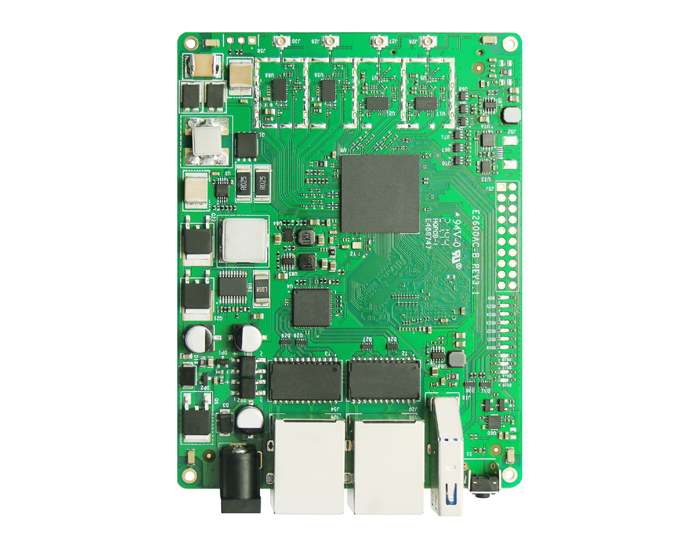
AJ-DLS150K-10 Device hardware signal

Serial number | port | Instructions |
1 | Ethernet1 | 4Pin ZH1.5mm seat, Ethernet port 1, and Ethernet port 2 are bridged internally |
2 | Ethernet2 | RJ45 socket, Ethernet port 2, and Ethernet port 1 are bridged internally |
3 | RS232*3 | 9PIN ZH1.5mm seat, 3 RS232 serial ports |
4 | Audio in/out | 4PIN ZH1.5mm seat, audio input/output interface |
5 | Power in | XT30PW-M seat, power input port |
6 | ANT1 | SMA threaded inner hole, the main antenna interface, the antenna for TDD transmit/receive mode |
7 | ANT2 | SMA external thread inner hole, auxiliary antenna interface, the antenna auxiliary receiving, not transmitting |
Ethernet port
Ethernet ports 1 and 2 are connected in bridge mode. Wireless network port IP data transparent transmission mode.

RS232 serial port
Three RS232 serial ports (D1, D2, D3), 9PIN ZH1.5mm pitch seat, PIN pin signals are shown in the figure below. Serial port D1 has the highest priority in wireless link data transmission (higher than audio and video data, network port data, and other port data), and the lowest delay. The D2 and D3 serial ports connect to the wireless network in network IP mode. The baud rates of the three serial ports and the D2 and D3 serial transmission modes can be configured on the Web UI. The D3 serial port can be reused as the management and configuration serial port of the AJ-DLS150K-10 system AT the same time, and the system parameter configuration query and management can be performed through the AT command through the serial port.

Audio in/out interface
Audio input/output interface, 4PIN ZH1.5mm pitch seat, each PIN pin signal see the figure above. The AJ-DLS150K-10 has built-in analog audio capture codec function, and the analog audio input is Mic in by default. Analog audio output is line out and can be directly connected to the headset. The control signal is used for On/Off control of the audio input. When the AJ-DLS150K-10 point-to-point wireless communication, the audio input and output interface can be used to directly carry out point-to-point bidirectional voice communication.
Signal pin | Signal specification |
IO | Control signal for audio inputOn/Off control |
GND | signally |
AI | Analog audio input pin |
AO | Analog audio output pin |
Working light

Power LED: Red power indicator, usually on during normal power supply.
Node LED: Blue node indicator. When the module is configured as the central node, it is always on. When the module is configured as an A-Node, it blinks.
Link LED: indicates the wireless link status indicator. Its working status is as follows:
Link LED | Status declaration |
Not bright | Indicates that the wireless link of the module is not connected |
red | Indicates that the wireless link of the module is connected, but the wireless signal strength is very weak |
orange | Indicates that the wireless link of the module is connected and the wireless signal strength is medium |
green | Indicates that the wireless link of the module is connected and the wireless signal strength is strong |
AJ-DLS150K-10 Equipment dimensions (mm)

AJ-DLS150K-10 device application
AJ-DLS150K-10 can realize long-distance two-way wireless data communication, which can be point-to-point two-way communication and point-to-multipoint two-way communication in star networking mode. In point-to-multipoint communication, if two A-nodes need to communicate with each other through the central node, all A-nodes share the wireless bandwidth with the central node in the same wireless LAN, and the device automatically distributes the system rate evenly. Data transmission from the central node to the A-node is called downlink, and data transmission from the A-node to the central node is called uplink. In point-to-point or point-to-multipoint communication, the downlink shares the wireless working bandwidth with the uplink. When the device is shipped, the ratio of upstream speed to downstream speed is set to 4:1 by default. Therefore, if the IP Camera video data is transmitted by the device, the IP camera should be connected to the A-Node. The device dynamically adjusts the wireless transmission rate based on the service data stream. The smaller the service data stream, the longer the transmission distance under the same conditions. Therefore, when the device is used to transmit IP Camera video data, the wireless transmission distance can be improved by appropriately reducing the IP Camera video coding rate.
Point-to-point wireless communication

Point-to-multipoint wireless communication

Relay mode

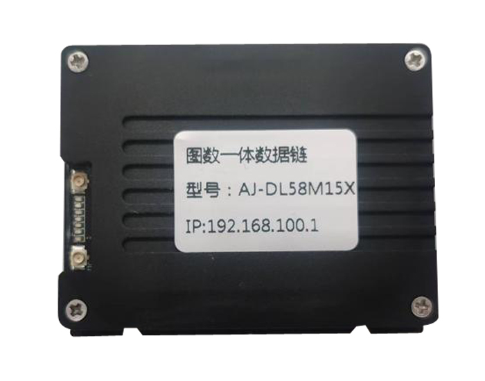 AJ-DL58M15X integrated data link
AJ-DL58M15X is a high-performance development platform with non line of sight wireless transmission capabilities. The AJ-DL58M15X adopts Qualcomm chip design for onboard 30dBm 5G 11AN;
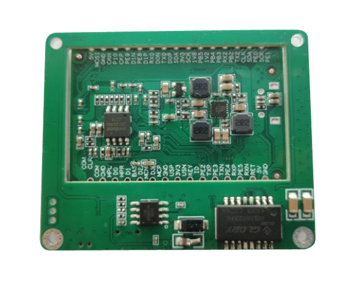 AJ-DL245 module
AJ-DL245 is a long-distance WIFI private protocol dedicated module designed based on 802.11, using Quanzhi V3S, ARM Cortex-A7, and up to 1.2GHz;
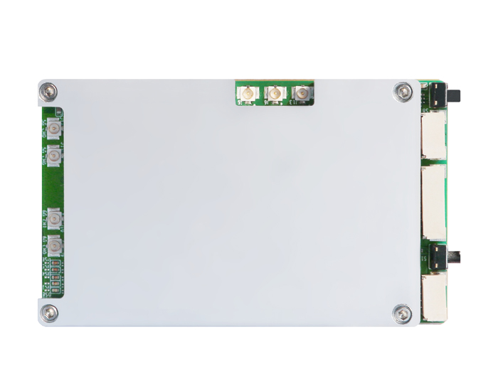
 AJ-DL582 Figure integrated data link
Long distance transmission: 2-5 kilometers in all directions (subject to changes in environment, weather, and other factors)
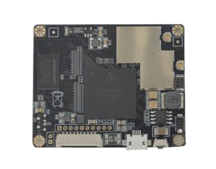
 AJ-DLM3X Figure integrated data link
AJ-DLM3X is a high-performance tri-band WIFI6 and WIFI6E ultra small industrial motherboard module designed with Qualcomm high-performance chips, with onboard 2.4GHz, 5GHz, 6GHz, and an effective throughput of up to 1Gbps. It supports WIFI6 proprietary technologies such as MU-MIMO and OFDMA
 AJ-DLS22K-2, 5 Industry HD photo transmission
Working frequency range: 1428-1448MHz Channel bandwidth: 1.4MHz/3MHz/5MHz/10MHz/20MHz Modulation method: QPSK/QAM16/QAM64
 AJ-DLS22K-10 Figure 1 Integrated data link device
The AJ-DLS22K-10 wireless link device achieves long-distance bidirectional wireless video, audio, and data transmission, with a maximum transmission distance of about 15km from air to ground.
 AJ-DLS50K-5 Figure 1 Integrated data link
Working frequency range: 1428-1448MHz Channel bandwidth: 1.4MHz/3MHz/5MHz/10MHz/20MHz Modulation method: QPSK/QAM16/QAM64
 AJ-DLSM2X-1 Figure integrated data link
AJ-DLSM2X-1 is a high-performance WIFI5 dual-band small industrial motherboard module, using Qualcomm high-performance chip design, on-board 2.4GHz, 5GHz, up to 600MBps effective throughput, support MU-MIMO
 AJ-DLSM2X-2 Figure integrated data link
AJ-DLSM2X-2 is a high-performance WIFI5 dual-band small industrial motherboard module, using Qualcomm high-performance chip design, on-board 5 GHz, up to 600MBps effective throughput
DL-DLS150K-10150 km industry class HD image transmission
AJ-DLS150K-10 wireless link equipment to achieve long-distance two-way wireless video, audio, data transmission, air-to-ground transmission distance up to 150km or so.
 Follow us